
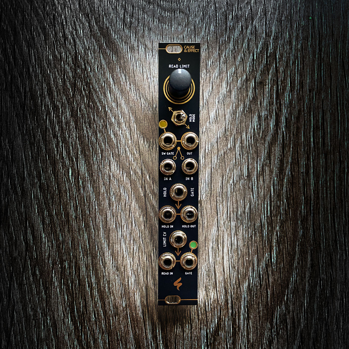

CAUSE & EFFECT - Voltage Reader, Sample & Hold and Gate Switch
FREE DOMESTIC SHIPPING ON ORDERS OVER $199
NO TAX ON ORDERS FROM STATES OUTSIDE CALIFORNIA (SHOP APP PURCHASES EXCLUDED)
3 units in one small package? Indeed!
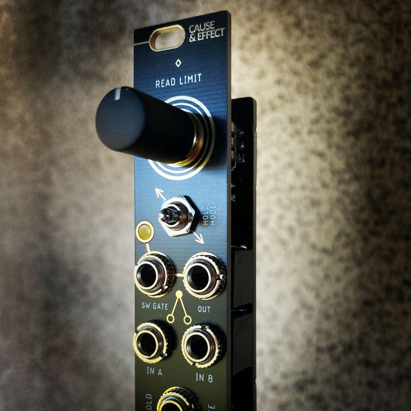
The first unit is a VOLTAGE READER, that outputs a gate signal according to a limit set with the help of the READ LIMIT potentiometer. If the limit set is reached by the incoming voltage, the R GATE output will be high. The limit may also be controlled via external control voltage at the LIMIT CV jack. This so-called comparator outputs a gate with an amplitude of +/-5V, which also makes it usable as a square wave generator with pulse with modulation via the READ LIMIT potentiometer. Any voltage applied to READ IN is normalised to HOLD IN and IN A. R GATE is normalised to H GATE and SW GATE. This way only one signal is necessary to control both other units.
The second unit is called HOLD. In one mode it can sample and store a voltage from the HOLD IN jack and supply it at the HOLD OUT jack, if gate at H GATE is high. In another mode it can pass through the incoming voltage when gate is high. It then samples and stores the last voltage value applied when gate switches to low. The modes are selectable via the HOLD MODE switch.
The third unit is a GATE SWITCH. Apply a gate signal to the SW GATE input to route IN A or IN B to OUT. If the gate signal is high, IN A is switched through, and if the gate signal is low, IN B is switched through. When only IN A is connected and IN B is not, OUT produces an inverted version of IN A when the gate is low, and a non-inverted version when high. When only IN B is connected and IN A patched with a dummy cable (a cable that is not connected to another module), IN B can be switched off by a gate signal. If nothing is patched to IN A, the VOLTAGE READER GATE output (J) is normalized to this input.
For more detailed information, make sure to refer to the CAUSE & EFFECT QUICK START GUIDE: click here
key features
-
Three Utility Tools
-
Voltage Reader for Gates
-
Hold for Sampled Voltages
-
Gate Switch
-
Gate Switch Inverter
-
Two Hold Modes
-
Inputs Normalised
-
Accepted input voltages for all inputs: -8V to +8V (CV & Audio).
-
Available in Intellijel and Pulp Logic Tile Format
-
Skiff friendly
specs & downloads
-
width: 4 HP & 20 HP
-
depth: 30 mm
-
power: 35 mA @ +12V / 31 mA @ -12V